The Noise Bridge
Some time ago I had built a noise bridge with the intention of using it to do antenna measurements on the HF bands, although it was never fully completed and had joined the pile of projects for a rainy day in the corner of the shack. Maybe this could be put to use on 500kHz? It was duly resurrected, calibrated and prepared.
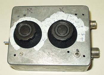
The design as shown on the right is based on one by John KI6WX which appeared in QST August 1989 - 'Improving and Using R-X Noise Bridges'. ARRL members can download the article from here. My version uses a different noise generator but is otherwise as per John's design. It has been calibrated using his technique to give the reactance in ohms relative to 10MHz. I use it in conjunction with my Datong U/C1 as a receiver.
It might have been thought that the noise bridge would be the ideal instrument for measuring impedance at 500kHz. I eagerly connected it to my antenna and twiddled the knobs - yes there was a nice null on the reactance control corresponding to 0 ohms, but turning the resistance knob I got no change and could only find a vague and very broad null if any. A few quick sums showed the reason. Most noise bridges find the zero reactance point against a fixed capacitor of half the value of the tuning capacitor - in my case 200pF. This capacitor has a relatively high reactance at 500kHz, 1,591 ohms. So for a 50 ohm load we are trying to match a resistive impedance of 50 ohms and a reactive impedance of 30 times that. No wonder the null is poorly defined and there is insufficient resolution. I tried various mods, including building a special version just for 500kHz, but in the end gave up. The noise bridge is not suitable for our job.
What the noise bridge is suitable for though is making measurements on the coaxial feeder. The most useful is a measurement of its electrical length, easy to measure with a ruler for a new run but not easy when it has been installed for many years. The procedure is described in KI6WX's article and involves short circuiting the remote end of the coax then finding the frequencies where the shack end impedance is zero, which correspond to multiples of a half wave. I found my coax had an electrical length of 14.7m, or a physical length of 22.3m assuming a propagation factor of 0.66. Other parameters which can be measured are the cable impedance and its attenuation factor.
The G3LDO 3M Impedance Bridge
Another way of measuring impedances is the so called '3 Meter' method. This method dates back to an article by W8CGD in QST June 1965. It was subsequently developed by Peter Dodd G3LDO and appears in his book 'The Antenna Experimenter's Guide' 1991 edition. A version for 136kHz was subsequently developed and details of this appeared on his website (site no longer available).
I had previously played with this method while setting up my 136kHz loop with limited success. The original 1965 design dated well before widespread use of computers and even digital multimeters. Its results were calculated by a graphical method using graph paper and the accuracy therefore left a lot to be desired - in particular if a sufficiently large excitation generator was not available there were very serious errors due to voltage drop across the RF detection diodes. Could this be improved?
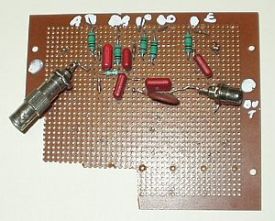
The G3YMC version of the 3M meter was built in my usual 'Ugly' style - no need for a fancy box for something which is only used occasionally. The only circuit changes were:
- The 1000pf diode probe capacitors were changed to 100nF
- OA91 germanium diodes were used - the OA191 originals are point contact
- The 20nF reference capacitor was changed to 5nF for 500kHz
- The input attenuator (15ohm resistors) was removed
I drove my 3M box from a Gould SSG220 synthesised RF generator, and measured the voltages at the probe points with my Fluke 77 digital meter. At its maximum output the voltages measured are a maximum of around 1V, considerably less than the 5V recommended level. G3LDO had used a low power transmitter, but it seemed somewhat antisocial to put that sort of power into the antenna just to do tests, so I decided to optimise it for the lower levels.
There are various programs available from the internet for the 3M bridge and these all work by simulating the original graphical solution method. The actual process is quite involved and because of lack of documentation the programs are hard to follow. It may be that it is easier to do the calculation by other methods when it is done by computer, but I decided to stick with the original. The code was rewritten in BBC Basic for Windows.
The initial tests I did with the 3M bridge showed that there were large errors in its measurements and it was soon realised that with the lower excitation levels the forward voltage drop of the detection diodes was a key factor. It may have been thought that adding the nominal knee voltage (300mV for a germanium diode) to each of the results would correct for this, but in fact when used as a peak detector the effective diode drop is much less. The program was modified to add a correction for the diode drop and to vary the value until good accuracy was obtained with a 50ohm load. It was found a correction factor of 64mV did the trick and using this value consistent results were obtained with accuracy within 1 ohm typically over a range of impedances.
A compiled version of my program is available here as g3ldo2.exe which can be run on any Windows PC. Operation is straightforward, just input the 5 probe voltages A-E in turn and the calculated impedance will be given together with an estimate of the error. Note that A-E correspond to EA,ER,ECZ,EC,EZ on G3LDO's schematic. Occasionally out of range measurements or impedances will produce an error and the program will exit. For convenience after each calculation the program loops for another run, to exit click the close button in the top right hand corner.
Remote Impedance Measurements
Wouldn't it be nice to make accurate measurements at the shack end of the coax, so much convenient than trying to do it at the antenna feed point itself? This was suggested in the original QST noise bridge article with instructions how to do so. The transmission line formulae are used to translate the impedance you see at the remote (shack) end of the coaxial line to what must be present at the antenna end. That article shows how to do it with complicated mathematical formulae, not for the faint hearted....
Thanks to our friend Reg G4FGQ (now sadly silent key) there are some very nice computer programs now available to do the job with a few clicks of the mouse. Two in particular are appropriate to our task - zl_zin.exe calulates the impedance at the antenna from the measured impedance at the shack end. input_z.exe does the reverse, ie what the shack impedance must be if you know the antenna end impedance. Both these can be downloaded from Reg's site along with all his other programs (note that Reg's site has now disappeared, the link is to a copy kindly provided by G3YXM).
So armed with these programs I set about trying to sort out my antenna matching. It soon became clear that this technique only produces accurate results if you know the exact characteristics of your coax cable. Since mine had long since been installed and had seen better days this was not so easy. I could easily find its length with my noise bridge as described above. The noise bridge also told me that it had a characteristic impedance of 49 ohms, pretty close to its presumed 50 ohms. But I could no longer remember what type of cable it was so I had no idea of what its propagation factor was. More significant, it became clear that the one thing that greatly affected the results was the cable attenuation. The program asks for the attenuation at 10MHz (which you can measure, not that accurately, with the noise bridge) and scales it to the figure at the frequency of interest. In my case the cable had seen better days and its braid was corroded, so it was probable that its loss was somewhat higher at 500kHz than a straight interpolation would indicate. Believe it or not the effect of 20 metres of cable at 500kHz is more significant than you would think!
Having struggled to make sense of my readings in the shack, tried various adjustments of the antenna matching transformer and other things, I was still no closer to having a properly matched transmitter, and the QSOs were pretty patchy. Once the rain had stopped for a while I bit the bullet and moved the signal generator to the bottom of the garden on a long extension lead to see what really was going on. I quickly had a 50 ohm match at the antenna, and having brought the gear back up to the shack found that I had the same there as well. Job done, and perhaps it shows that trying to do remote measurements is not the quickest way... In the process I also found that my transmitter was going unstable when seeing a proper 50 ohm load which had been confusing me just a little - a mod to the transmitter soon sorted that out.
Some people may find the remote impedance measurement technique useful, but don't rely on it. Having done it the proper way down the garden I now found the QSOs were coming in fast and furious and the system was working at last.
Update May 2009
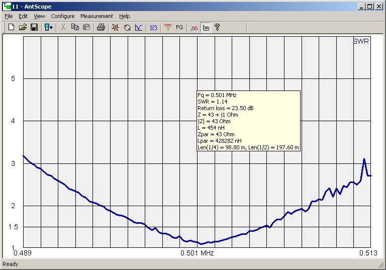
In 2009 I invested in a Rig Expert AA200 analyser. The antenna, which had been in its top band configuration for some time, was reconfigured for 500kHz, the transmitter was resurrected from the cupboard, and I now set about matching the vertical properly.
These modern analysers certainly make the job of matching a doddle. In no time at all I found the variometer had slightly too much inductance and was resonating around 460kHz, so a few turns of wire were removed. The tuning is quite critical with just a small adjustment making a substantial shift in the resonant point. It was soon tweaked to 502kHz. The impedance as seen at the matching transformer primary was also a little low, around 30 ohms, so a couple of turns were removed from the secondary side - now around 48 ohms, near enough as it was bound to change as the ground resistance changed in wet weather. All is now in order. I would like to have said that QSOs were coming in fast and furious, but activity seems to have totally gone away... The screenshot (using the AA200 PC software) shows the matching condition.