 |
A 10MHz drive signal is taken from the low power output socket of my FT101ZD, terminated in 50 ohms and attenuated to a suitable level for applying to the gate of the dual gate MOSFET mixer stage. An injection signal is applied to the second gate from the crystal oscillator. The drain is connected to a parallel tuned circuit at 136, whose output is buffered by an FET source follower and fed to the transmit driver stage. |
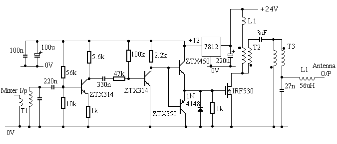
The low level input from the transmit mixer is passed through a 136 tuned stage and then amplified by a two transistor amplier to produce a 12V square wave drive level which is buffered by dual emitter followers and applied to the gate of the power MOSFET. These low level stages are powered by a 12V rail derived from the 24V pa rail via a 7812 regulator.

| The output amplifier consists of a single IRF530 MOSFET run off a supply
of 24V. The current taken and the output power is determined by the
impedance matching, which transforms the 50 ohm load impedance to around
3 ohms at the drain of the FET.
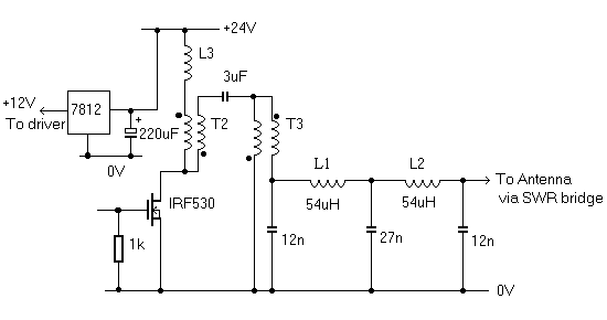
T2 and T3 are bifilar wound transformers on 3C85 ferrite rings, each transformer being configured for an impedance transformation of 4:1. The output is low pass filtered by the 56uH inductor and associated capacitors. Suitable cores for T2 and T3 are Philips 4330-030-34480. The choke L1 is for stability purposes and consists of 12 turns of wire on a 25mm ferrite ring. The transmitter outputs around 35 Watts into a resistive load. When using a real antenna the impedance will differ from 50 ohms over the operating range and the output will change accordingly. The transmitter requires a power supply of 24V at a current of 4A maximum.
|
 |
This simple SWR/Power meter can be used as a tuning aid. The value of the AOT resistors depends on the sensitivity of the meter, and is typically about 10kohms - adjust for full scale deflection in the forward direction. T1 and T2 are wound on the same 3C85 torroids as used in the transmitter. The diodes should be point contact or germanium ones with low forward voltage drop (eg OA91). |
Alternative Transmit Drive Circuit
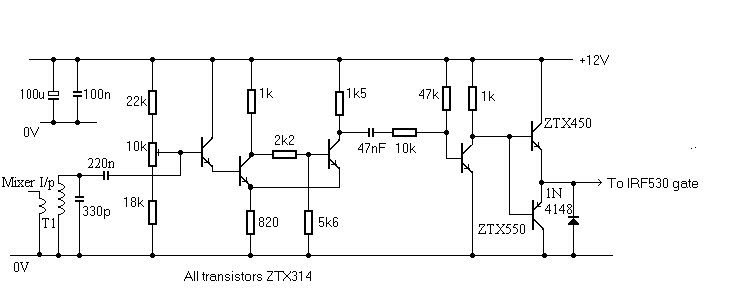
| The circuit shown here has been developed as an alternative
drive circuit for the FET pa. This circuit uses a Schmitt trigger
to maintain an approximate square wave drive waveform to the output FET
independent of the input level from the mixer. Fine adjustment of
the Schmitt threshold via the 10k pot allows the mark space ratio to be
optimised.
This circuit is used in the present version of my transmitter. |
 |
| The output stages have also been slightly changed, and there is now a proper low pass filter ensuring the output waveform is sinusoidal. |
 |
| 136kHz Main Page | Loops | Equipment Practices | Receiver | Home Page |