The G3YMC antenna
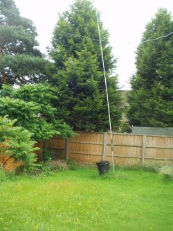
At G3YMC the options for antennas are rather limited, as you will know if you have been reading the rest of this site. With a 45ft x 22ft back garden there is really not much you can do with antennas, and since I am active on the other amateur bands any additional antenna must not affect those. As well as a bent 110ft low long wire which could have been used I have for some years been using a Butternut vertical on 160m. I had in fact used this for a short time on 136kHz with limited success. A few quick calculations with G4FGQ's vertload program showed this should give acceptable results, with around 1% efficiency. On 136kHz I had used it with a horizontal top loading wire otherwise the loading coil would have been unrealistically large. But any top loading wire would get in the way of my longwire and other antennas so it was decided to initially do without one. The NOV was accordingly prepared assuming this antenna, as shown in the photo with the dustbin containing the loading coil and matching network at the side.
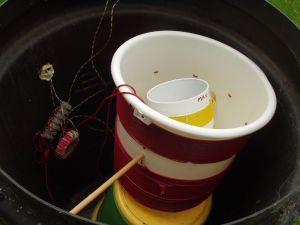
The calculations with Reg's program showed I would need about 1mH to resonate my vertical on 500kHz, assuming I added the additional inductance in series with the existing Top Band loading 1m above ground. For mechanical reasons it is not possible to put a loading coil of this size any higher. I looked around for a suitable coil and by luck came across the variometer which Steve GW4ALG had given me years ago for use on 136kHz. It needed a bit of work on it as it had been neglected in storage for a long time and some of the windings had slipped out of place. It turned out to be ideal for the purpose, being a variable inductor of between 600uH and 1mH.
Having sorted out the variometer it was fairly quickly mounted in my dustbin (on top of the two coils still there from its 136kHz days..) and wired in series with the existing loading coils on the vertical. Initially the coax feed from the shack was connected directly to the base with no matching network. It was known this would not be a good match but it would suffice for receive purposes. Although the resonant point was fairly broad the difference from my untuned longwire was very noticeable and I now had a very lively receiver on the band.
Having got the receive side going quite nicely and hearing quite a lot of activity on the band it was time to get cracking with the transmitter. This took a few weeks, and you can see my design on the transmitter page. Eventually it was completed and the time came for the acid test, would it actually work. Disappointment, there was an almost infinite SWR....
Then began a long process to attempt to measure the impedance of the antenna and its resonance. See here for a detailed analysis of impedance measurements on 500kHz. In the end I used G3LDO's 3-meter method. Initial results of my tests showed that the feed impedance at the antenna was of the order of 300 ohms - no wonder it didn't match... but after some measurements and adjustments I got it down to 145 ohms - not good but at least I was having QSOs.
The root cause of my problems was clearly the earth resistance. I had similar problems on 160m and got round the problem there by laying a chicken wire mat on the lawn during the winter months. In summer this is not possible as I need to mow the lawn. Perhaps the addition of some earth spikes would help and I intend to try this later on. For the moment I accepted that I had a lousy earth but was itching to try my transmitter out! To produce the correct 50 ohms impedance I connected a matching transformer wound on a ferrite ring with the correct turns ratio. I now found the match was reasonable and I was able to verify the resonance of the antenna.
Initial results have been disappointing. I have had a few reception reports from more local stations and I have been able to work G3XIZ in Biggleswade with reasonable signals. But reports from further afield have been very poor with my signal just discernable above their noise level. Clearly more work is needed to reduce the earth losses, and I intend to do this in the coming months. Watch this space!
Update July 2007
After antenna adjustments as described on my Impedances page, together with some small changes to the transmitter to cure instability and increase output power I have now got my station working quite well. The measured earth loss is 150 ohms and for an output power of around 6W the estimated ERP is 5mW - not good but it has allowed me to have some quite good QSOs. I can now easily work stations in the 100-150 mile range, but there remain some of the more distant ones I cannot reach. You can find a list of all the stations I have worked on my activity page.
Activity on the band seems to have dropped off somewhat at the moment, possibly as the initial enthusiasm for the new allocation wanes. But when the winter months approach there will be more opportunities for longer distance QSOs during the night time hours, as like Top Band I suspect conditions will be far better then. I hope to work on continue improving my antenna and reduce the earth loss, and will update this site periodically.
Update May 2009
I didn't get on the band during 2008. I did temporarily connect up the antenna but I found that it didn't match and never got round to finding out why. In 2009 I invested in a Rig Expert AA200 analyser and that gave me the impetus to have another go. As you will see on my Impedances page it was a doddle to get the antenna resonated and matched with the new analyser so I am now all set up to make QSOs. But apart from the G4JNT beacon which is now operational there seems very little other CW activity. But hoping to change that before I put the antenna back to its top band settings next winter.